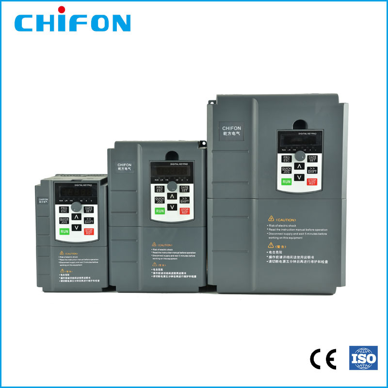
5

  ICM Industries   SA Alternator for Generators

Midrand  SA Gauteng South Africa  

          www.icmsa.co.za              011-312 3393,    011-312 4877 Only if land line not working call 0606107549, What's App no Also 0606107549.

 Variable Motor speed Controls

 Vector AC Drive

Variable motor speed control 2.2 KW 220 Volts R2495+VAT

Variable motor speed control 15 KW 380 Volts R9495+VAT

FPR High performance closed loop vector converter

Power class

Single-phase 220v±15% 0.4-2.2kw
Three-phase 380V±15% 0.75-315kw

Product introduction

FPR500 series relies on TI company's DSP dual-core professional

control motor chip,

which supplies the international leading vector control algorithm to

realize the real high-precision flux vector torque control. It has

built-in pg vector control (VC), pg - free vector control (SVC) and

V/F control modes, which widely aplied to high speed control

accuracy, rapid torque response and high performance at low frequency. 

The integration of torque control, speed control and position control

can meet the high performance requirements of customer applications. 

And, FPR 500 has the ability to exceed the anti-trip performance of

similar products and adapt to severe power grid, ambient temperature, humidity and dust, greatly

improving the reliability of products.

Technical characteristics

Drive motor type: Ac asynchronous motor, Ac permanent magnet

synchronous motor
Four control modes: PG vector control (FVC), PG- free vector control

(SVC), V / F control, Torque control
Speed control range: PG vector control(FVC)1:1000
PG- free vector control(SVC)1:200
V / F control 1:50
Speed control accuracy: PG vector control (FVC)±0.2%
                     PG- free vector control (SVC)±0.5%
Starting torque: PG vector control (FVC):180 % rated torque/0.01Hz
              PG- free vector control (SVC)150% rated torque/0.25Hz
Torque control accuracy: PG vector control (FVC)±5%
                     PG- free vector control (SVC)±8%
Multi - motor switching: Two groups of motor parameters can realize the switching

 control of the two motors.
Motor overheating protection: Optional IO expansion card, analog

A / 3 can accept input from motor temperature sensor


Supports multiple encoders: Supports differential, open collector, uvw,

rotary transformer, sine and cosine encoder
Torque limitation and control: the "excavator" feature, automatically

 limits

the torque during operation to prevent frequent over current trips.

Closed loop mode can realize torque control.
 

Permanent magnet motors

Double bearing electric 3 phase motors are high efficiency rare earth permanent magnet 

synchronic motors, the efficiency is IE4.

Special price 19 April 2024       For Sale
Copper winding.   One year warrantee

          All 1500 R.P.M   Brushless    

   Stock arrived.  we do not stock any other size.

Permanent Magnet Electric Motor  

(kW)


(KVA)


 Volts

Double Bearing Price excl VAT In

stock

           
 PMEM 4.8 4 5 380 V R 14,500 5
           
           
PMEM 8 8 10 380V R 19,995 5
PMEM 12 12 15 380V R 28,495 2
 

e mail:  icm@lantic.net


Direction: On Google Map you can search for ICM Industries and drive here.

Variable Motor speed Controls sa
Basic Function Specification
Maximum output frequency 0~500Hz
Carrier frequency 0.5kHz~16.0kHz;According to the load characteristics, carrier
frequency can be adjusted automatically
Input frequency Range :47~63Hz
Control mode V/F   Open/closed loop vector control's/FVC)
Speed range 1:50(Vector mode 0 ) 1Hz/150% rated torque
Overload

capability

G type:150% rated current for 60s;   
180% rated current for 3s
P type:120% rated current for 60s;
150% rated current for 3s
Torque boost Auto Torque boost Manual Torque boost; 0.1%~30.0%.
V/F curve V/F Four modes : Line , Multi-point , Square V/F curve, V/F separation
Jog control Jog frequency range:0.00Hz to F0-10(Max frequency)
Accelerate/

Decelerate curve

Line or S-curve Acc/Dec mode, four kinds of Acc/Dec time Range
of Acc/Dec Time0.0~65000.00s.
DC brake DC brake frequency: 0.00Hz to Maximum frequency
brake time: 0.0 to 36.0s
brake current value: 0.0 to 100%
Simple PLC,

Multi-speed

16-speed operating through built-in PLC or control terminal
Built-in PID Close loop control system can be formed easily by using PID
Automatic voltage
regulating (AVR)
Output voltage is regulated when voltage of the power network changes
Overvoltage and over current
stall control
During operation automatically limits the inverter output current
and bus voltage, to prevent fan over current and overvoltage trip.
Rapid current limiting
function
Minimizing flow failures, protect the normal

operation of the inverter

Instantaneous stop non-stop Load feedback energy compensation voltage is reduced and continues to maintain a short time when change is momentarily interrupted.
Speed tracking

start

For high-speed rotation of the motor speed identification, impact-
free smooth start
Rapid current limit Rapid software and hardware limiting technology to avoid
frequent converter over current fault.
Virtual IO Five sets of virtual DO, five sets of virtual DI,

enables easy logic control.

Timing Control Timing control: set the time range 0.0Min~6500.0Hour
Multi-motor
switch
Two independent motor parameters, enabling

two motors switching control

Bus Support Two independent Modbus communication, CAN-Link
Command source Given the control panel, control terminal, serial communication port given. It
can be switched by a variety of ways.
Torque boost Auto Torque boost Manual Torque boost  ; 0.1%~30.0%.
Frequency source Nine kinds of frequency sources: digital setting, analog voltage setting, analog current setting,

pulse setting, or serial port and so on. It can be switched by a variety of ways.

Auxiliary
frequency source
Nine kinds of auxiliary frequency source. Flexible implementation of auxiliary
frequency tuning, frequency synthesis.
Input terminal Six digital input terminals, one only supports 50khz high pulse input
Two analog input terminals, one support 0V~10V voltage input
One support 0 ~ 10V voltage input or 0 ~ 20mA current input
Output
terminal
One high-speed pulse output terminal (optional

open collector type), support of square wave 0 ~ 50kHz signal output
One digital output terminal
One relay output terminals
Two analog output terminals, support 0 ~ 20mA current output or 0 ~ 10V
voltage output

Display and operation
LED display Display parameters and status information
The key lock and

function selection

Achieve some or all of the keys locked, scope definition section keys
to prevent misuse.
Protection function Input/output phase failure protection ,Over current protection ;Over
voltage protection; Under voltage protection; Overheat protection ;
Overload protection
Options Brake assembly, PG card
Environment
Application

environment

In-door, free from direct sunlight, dust , corrosive gas, combustible gas, oil mist ,

steam , water drop and salt .

Altitude Lower than 1000m
Vibration Less than 5.9m/s(0.6g)


 ICM Industries


7 of 73 Capital Hill park inside, Capital Hill commercial Estate 395 Le Roux st Midrand South Africa


 Tel:  060 610 7549 If busy please retry in 5 minutes.


Homepage: http://www.icmsa.co.za

e-mail: icm@lantic.net

Please let us know your opinion about our business and any web problems by mentioning page name to web Master.           Thank you